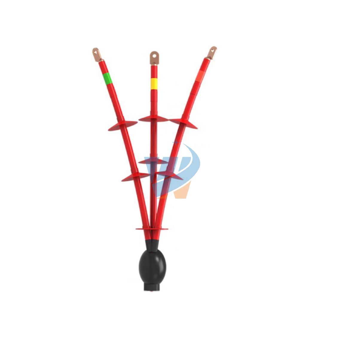
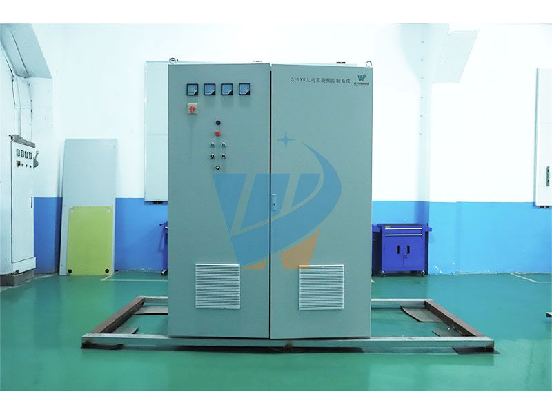
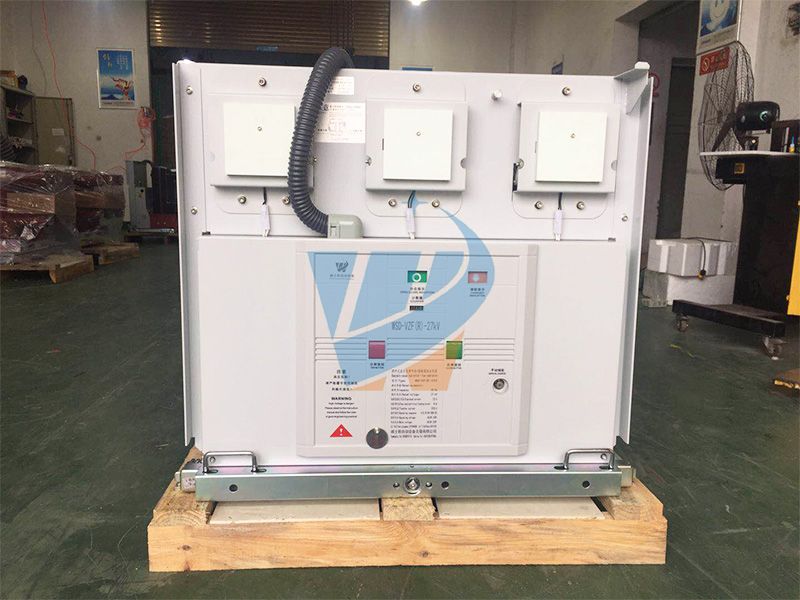
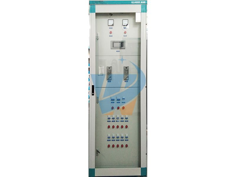
wsd power distribution cabinet
I. Overview
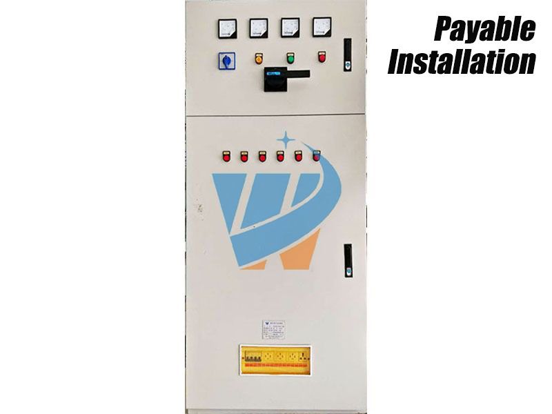
XL-21 low-voltage power distribution cabinet is suitable for power plant, industry and mining enterprises. It is used for power distribution in three-phase four-wire or three-phase five-wire system with AC voltage of 500V or less. XL-21 low-voltage power distribution box is installed on the wall of the indoor device and repaired in front of the screen.
Ⅱ.Type and Meaning

Ⅲ.Structural characteristics
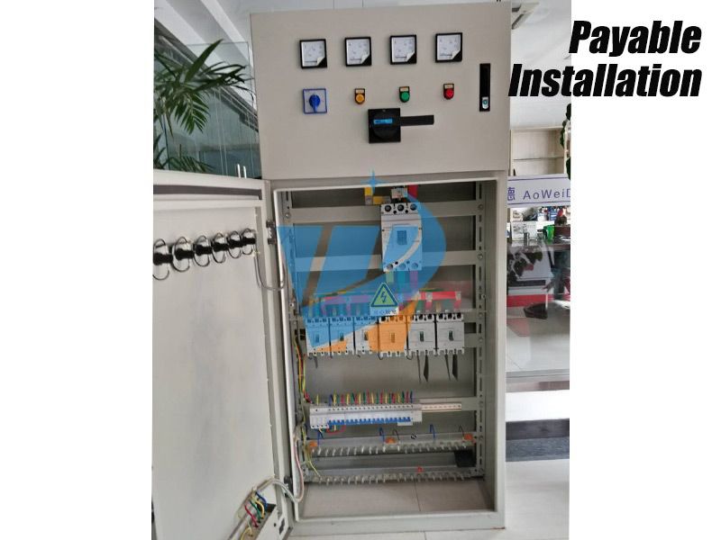
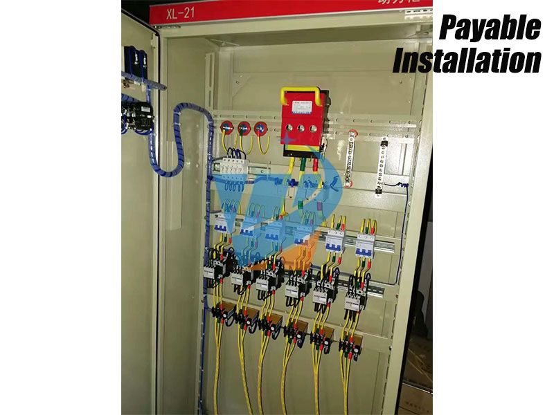
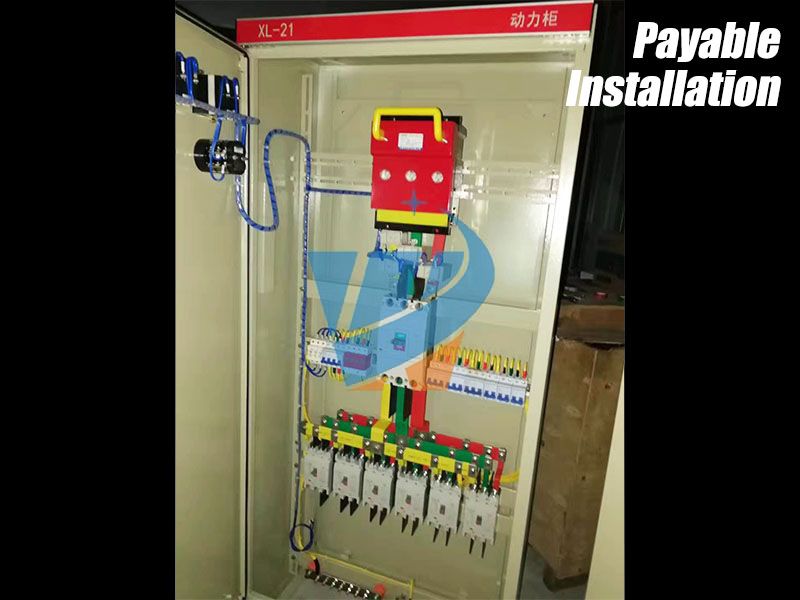
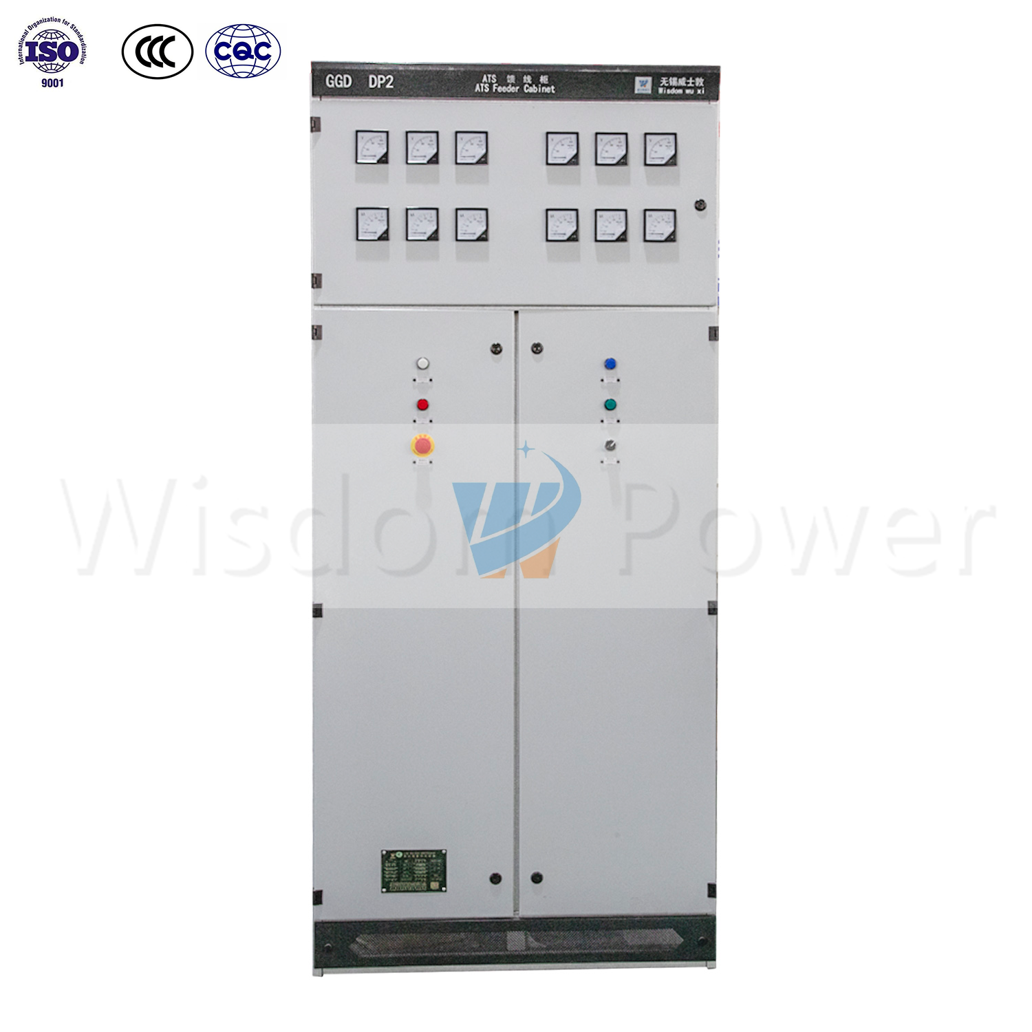
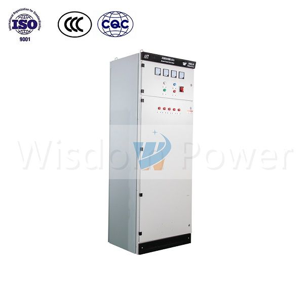
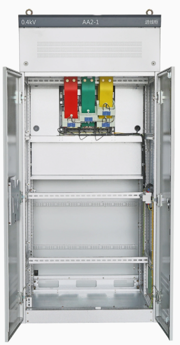
XL-21 low-voltage power distribution box is closed, the shell is formed by bending steel plate, and the knife switch operating handle is located at the upper part of the right column in front of the box, which can be used for switching power supply. A voltmeter is installed in front of the distribution box to indicate the voltage of bus bar. There is a door in front of the distribution box. When the door is opened, all the equipment in the distribution box is exposed, which is convenient for maintenance. The distribution boxes adopt domestic self-designed components, which have the characteristics of compact structure, convenient maintenance and flexible combination of line schemes. Distribution box is equipped with air circuit breaker and fuse as short circuit protection. Contactors and thermal relays are also equipped. The front door of the box can be equipped with operation buttons and indicator lights.
Power Distribution Cabinet
The power distribution cabinet (box) is divided into a power distribution cabinet (box), a lighting distribution cabinet (box), and a measurement cabinet (box), which are the final equipment of the power distribution system. The power distribution cabinet is the general name of the motor control center. The power distribution cabinet is used in occasions where the load is scattered and there are few circuits; the motor control center is used in the occasion where the load is concentrated and there are many circuits. They distribute the electrical energy of a circuit of the upper-level distribution equipment to the nearest load. This level of equipment should provide protection, monitoring and control of the load.
Definition Power Distribution Cabinet
Respectively refer to the final equipment of the power distribution system such as power distribution cabinet, lighting distribution cabinet and metering cabinet.
Grading of Power Distribution Cabinet
(1) The first-level distribution equipment is collectively called the power distribution center. They are installed centrally in enterprise substations and distribute electrical energy to lower-level distribution equipment in different locations. This level of equipment only depends on the step-down transformer, so the electrical parameters are higher and the output circuit capacity is also larger.
(2) The secondary power distribution equipment is the general name of power distribution cabinet and motor control center. The power distribution cabinet is used in occasions where the load is scattered and there are few circuits; the motor control center is used in the occasion where the load is concentrated and there are many circuits. They distribute the electrical energy of a circuit of the upper-level distribution equipment to the nearest load. This level of equipment should provide protection, monitoring and control of the load.
(3) The final power distribution equipment is collectively called the lighting power distribution box. They are far away from the power supply center and are scattered small-capacity distribution equipment.
Commonly used
Main switchgear type of Power Distribution Cabinet:
Low-voltage switchgear has GGD, GCK, GCS, MNS, XLL2 low-voltage distribution box and XGM low-voltage lighting box.
The main difference:
GGD is a fixed type, and GCK, GCS, and MNS are drawer cabinets. GCK and GCS, MNS cabinet drawer propulsion mechanism is different;
The main difference between GCS and MNS cabinets is that GCS cabinets can only be used as single-sided operation cabinets with a depth of 800mm, and MNS cabinets can be used as double-sided operation cabinets with a depth of 1000mm.
Pros and cons :
Withdrawable cabinets (GCK, GCS, MNS) are more economical and convenient to maintain, with more outlet lines, but expensive to manufacture;
The fixed cabinet (GGD) has relatively few outlet circuits and a large footprint (it is recommended to use a drawer cabinet if the fixed cabinet cannot be made in a small place).
Installation of Power Distribution Cabinet
The installation requirements of the distribution board (box) are: the distribution board (box) should be made of non-combustible materials; production sites and offices with low risk of electric shock can be installed with open-type distribution boards; Poor processing workshops, casting, forging, heat treatment, boiler rooms, carpentry rooms, etc., should be installed with closed cabinets; in hazardous workplaces with conductive dust or flammable and explosive gases, closed or explosion-proof type must be installed Electrical installations; the electrical components, meters, switches, and wiring of the distribution board (box) should be neatly arranged, firmly installed, and easy to operate. The bottom surface of the board (box) installed on the floor should be 5~10 mm above the ground; the center height of the operating handle is generally 1.2~1.5m; there is no obstacle in the range of 0.8~1.2m in front of the board (box); the protection line is connected reliably; the board There shall be no bare live exposed outside the (box); the electrical components must be installed on the outer surface of the board (box) or the power distribution board, and there must be reliable shielding.
How Power Distribution Cabinet working
The electrical components and circuits in the distribution board (box) should be in good contact and reliable in connection; there should be no severe heat generation or burning damage. The door of the distribution board (box) should be intact; the door lock should be kept by a special person.
The circuit diagram of the distribution board is divided into a primary schematic diagram and a secondary schematic diagram. The primary schematic diagram is the main circuit schematic diagram. The secondary schematic diagram is the schematic diagram of the control circuit.
The intelligent integrated power distribution cabinet has made great improvements compared to the previous power distribution cabinets! It is a technological innovation!
Aiming at the current situation that the power distribution of the equipment room is prone to single-point failures, it integrates the most advanced technical achievements and hardware and software designs in one. Committed to bringing a new experience to the construction and management of power distribution in the computer room. It is mainly used in data centers and computer rooms such as finance, telecommunications, enterprises, and governments. The capacity range is 30KVA-160KVA. The entire power distribution system uses a standard network cabinet and modular structure design, with a wealth of optional accessories, according to the actual needs of the computer room, customized high-reliability products for customers.
The intelligent distribution cabinet monitors the current of each output branch in real time, and can set the pre-alarm value of each output branch current abnormality, such as 16A switch, set the alarm value to 14A, then the load exceeds 14A and it will alarm, and the fault can be found in advance Or man-made hidden dangers, when the overload is avoided, the switch cuts off the power supply,
Distribution Cabinet
Power off the entire cabinet equipment. In addition, the hot-swap circuit breaker is used for the output shunt, which has the ability to adjust the power phase, which can easily realize the flexible adjustment of the 3-phase imbalance. It can also increase the output shunt online and switch replacement under the condition of continuous power.
Features
The product also uses a large-screen LCD touch screen to monitor the power quality of voltage, current, frequency, useful power, useless power, electrical energy, and harmonics in an all-round way. Users can see the operation status of the power distribution system in the computer room at a glance, so as to find hidden safety hazards early and avoid risks early.
In addition, users can also choose ATS, EPO, lightning protection, isolation transformer, UPS maintenance switch, mains output shunt and other functions to ensure the safety and stability of the computer room power distribution system.
Operating procedure
1. The power distribution cabinet is the normal operation of the ship's power distribution center and the equipment. Any unrelated personnel shall not pull the switch on the board.
2. After the generator set is started, the power screen speed-up switch should be used to slowly accelerate manually until the generator enters the normal working state, and the voltage and frequency reach the specified values before closing the power supply.
3. After the power distribution board enters the power distribution state, the power screen speed-up switch shall not be pulled at will, and the blocking switch of the air circuit breaker shall not be used in non-emergency situations.
4. The parallel operation of generators must be operated in strict accordance with the requirements and regulations of paralleling conditions, and attention should be paid to the occurrence of reverse power (countercurrent) and failure of paralleling.
Fifth, the load of the generator should be cut off before stopping, and then stopped with no load, and it is not allowed to stop directly with load.
6. When inserting the shore power, the power switches of the shore power screen should be cut off first, and then check the correctness of the wiring and phase sequence. After confirming the correctness, the conversion of the ship's shore power can be implemented, and operation with load is strictly prohibited.
7. The power distribution cabinet should be cleaned and maintained regularly to keep the equipment in good working condition.
8. When the generator is working, the turbine personnel should focus on the operation of the switchboard, and operate carefully to prevent accidents. Otherwise, personal accidents will be held accountable.
9. The charge-discharge board is a ship's emergency power distribution board. The on-duty engine crew should always check their working conditions to ensure that the low-voltage power is sufficient at all times, and grasp the working state of the magnetic saturation regulator through the on-board instrument.
10. During normal navigation, the switches on the distribution board should be connected to ensure that the generator can be started at any time and can be put into use at any time as required.
11. The above points hope that the members of the Ministry of Rotation strictly abide by them.
Distribution Cabinet
Secondary wiring process
1. According to the schematic diagram, the terminals that are not in the same position should be connected to the terminal. Never connect 3 wires to one terminal. If you check the error, it is not so easy to check, you can only follow the schematic diagram one by one.
1. Selection of conductor cross section
The line of the mains (AC 220V) voltage loop is 1.5 square millimeters; the current loop is 2.5 square millimeters. The battery generally uses 1.5 square millimeters.
2. When wiring, check whether the signals on both ends of the wire correspond to avoid unnecessary errors.
3. The most important thing is to understand the schematic diagram and wiring diagram.
2. If you are a novice, you need to review the drawings first, and sort out your own ideas. You can also check whether the drawings have any problems. If you don’t understand, you can understand it first, which is conducive to making lines. Only then did the wiring begin. The entire wiring process needs to be careful, of course, if you are a veteran, you don't need to say so much.
The construction personnel should carefully read and be familiar with the symbols of the secondary line, and check the secondary wiring diagram with the schematic diagram to ensure that the wiring diagram is correct.
Requirements for secondary wiring construction: construction according to the drawing, correct wiring; wire and electrical components are bolted, plugged, welded or crimped, etc., all should be firm and reliable, and the wiring is good; wiring is neat and clear, beautiful; wire insulation , No damage; there should be no joints in the wires in the cabinet; the loop number is correct and the writing is clear.
The selection of cable core cross-section should also meet the following requirements:
(1) Current loop: The working accuracy of the current transformer should be made. At this time, if there is no reliable basis, the maximum short-circuit current can be determined according to the current capacity of the circuit breaker.
(2) Voltage circuit: When all protection devices and safety automatic devices are activated (considering development, when the load of the voltage transformer is the largest), the voltage drop of the voltage transformer to the protection and automatic device screen should not exceed 3 of the rated voltage %.
(3) Operation loop: Under maximum load, the voltage drop from the operation bus to the equipment should not exceed 10% of the rated voltage.
The secondary winding of the current transformer is not allowed to open. No short circuit allowed on the secondary side of the voltage transformer
Before secondary wiring, familiarize yourself with the drawings:
1. Schematic diagram. (Indicates the working principle and interaction of each circuit. The drawing soon shows the connection method of each component in the secondary circuit, and also shows the connection with the primary circuit)
2. Expanded view
3. Terminal block diagram
4. Installation wiring diagram


